Recaping a Lando LX4000 frequency divider
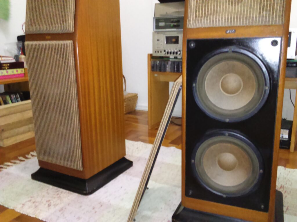
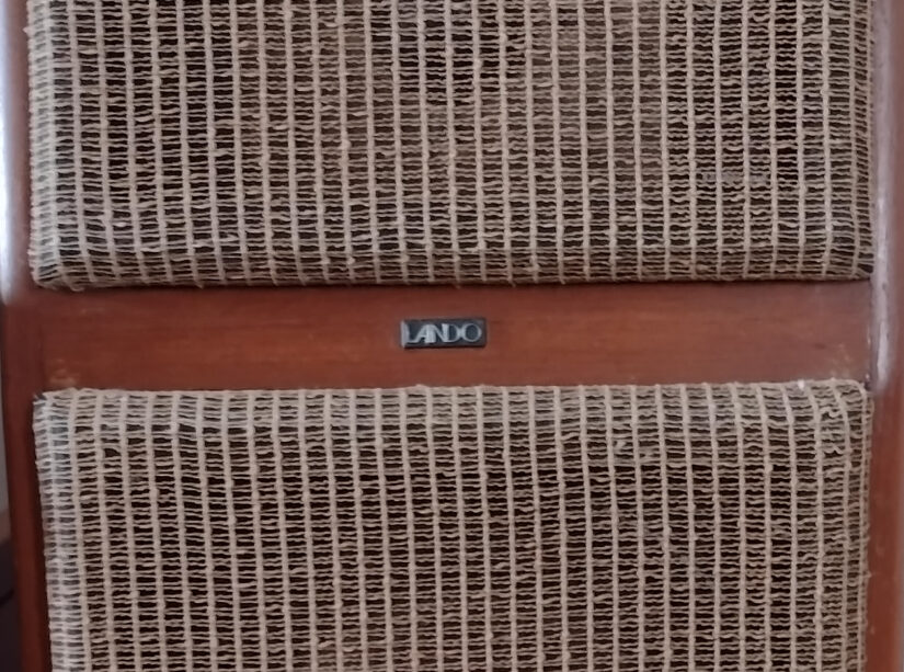
Lando is a brazilian hifi loudspeaker systems manufacturer founded in late 70s by two german business partners. I’ve acquired a pair of their LX4000 model in 2015 from a nice guy who shared their whole history since he purchased them from a local store in the early 80s.
Last updated on January 31st, 2022
*** Page Under Construction ***
The previous owner didn’t change anything except for the front brown grill cloth (originally in black), which I knowledge it turned out into a much better looking piece, thanks to his wife! On the first listening inspection I gave, it was clear some high frequencies were abcent or attenuated. Not surprised since it obviously needed a recap. So I’ve bought it anyway!
General Specifications
The LX4000 model is a three-way system with the following specs.
| Reference | Description |
| Model | LX4000 |
| Impedance | 4 Ω |
| Maximum Power | 100WRMS / 140WIHF |
| Frequency Response | 20Hz – 25kHz |
| Woofer | 8” / 200mm speaker (x2) |
| Midrange | 1.5” / 38mm speaker (x1) |
| Tweeter | 0.75” / 19mm speaker (x1) |
The frequency divider board
The loudspeaker has the task of converting the electrical signals from the power amplifier back into a faithful reproduction of the input source sound. In multi-way speaker systems, a frequency divider circuit is designed to ensure that each speaker receives only the signals it is required to reproduce.
The LX4000 frequency divider is shown in the schematics below.
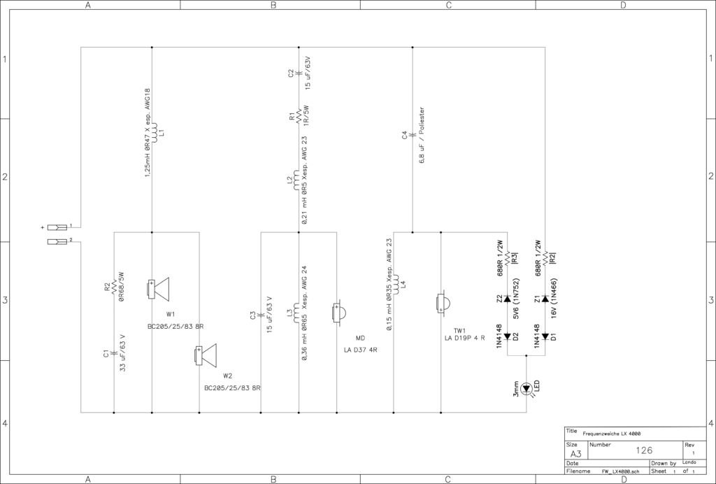
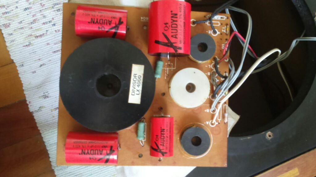
The pictures below shows the frequency divider board found in my LX4000.

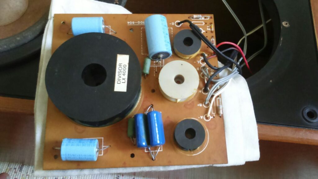
The first set of replacement capacitors I bought were from Audyn. It was good to hear the absent frequencies back and I felt good for a few weeks. But, despite of having asked for matched capacitors (very important), the speakers didn’t seem to sound identical to each other. For this purpose I highly recommend 1% tolerance components at most.
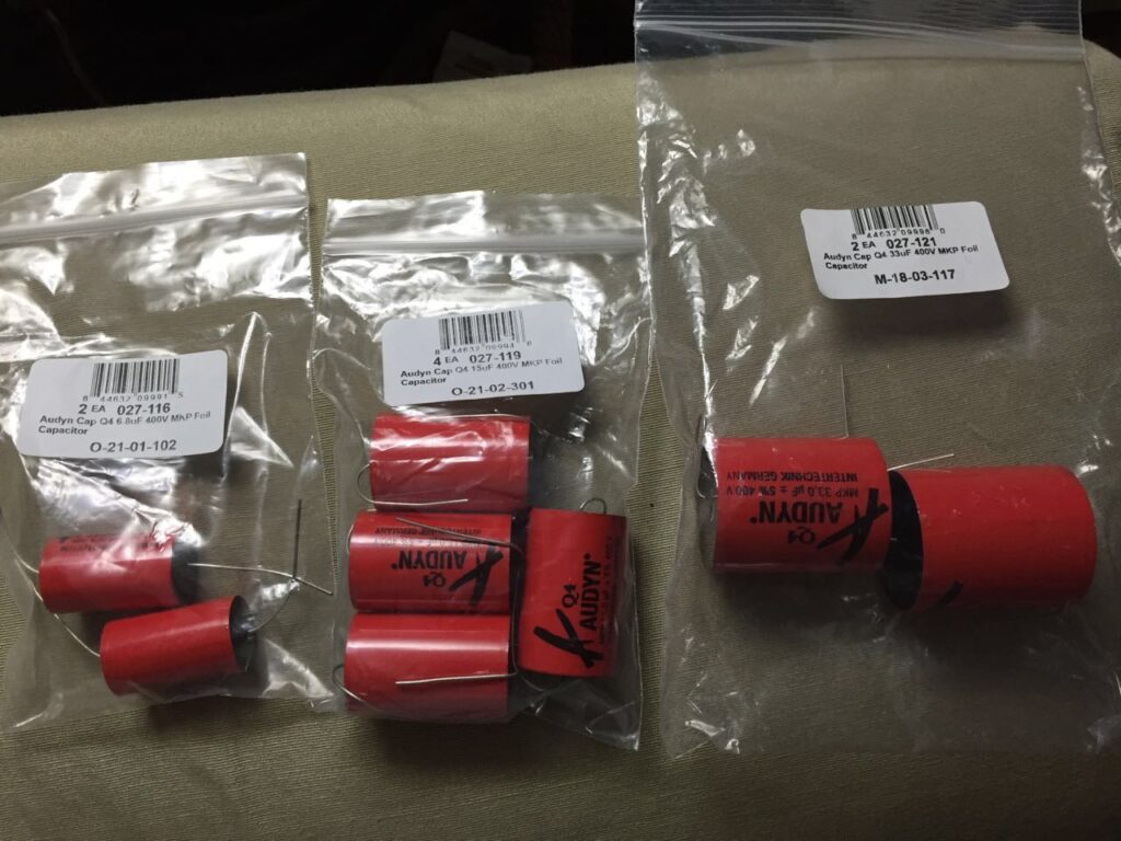
Later on I decided to buy another set of capacitor, this time from Dayton Audio, with a 1% deviation tolerance from nominal values. There were only 5% tolerance for the 33uF capacitors. Another issue was their sizes. The 33uF caps were too big for the space on board. I wasn’t able to replace them in a decent way so left them for another day.
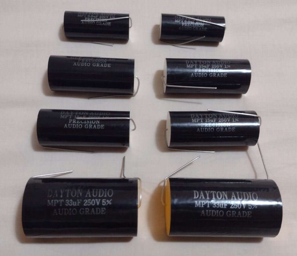
| Schematics Board | Board Reference | Replacement | Quantity | Notes |
| 33uF, 63V 33uF, 63V, 10% | C1 | 33uF, 400V, 5% Audyn MKP | 1 per board | Replaced. To be replaced by Dayton caps |
| 15uF, 63V 15uF, 63V, 10% | C2, C3 | 15uF, 250V, 1% Dayton Audio MPT | 2 per board | Replaced |
| 6.8uF, 50V 2x 3.3uF, 250V, 10% | C4 | 6.8uF, 250V, 1% Dayton Audio MPT | 1 per board | Replaced |
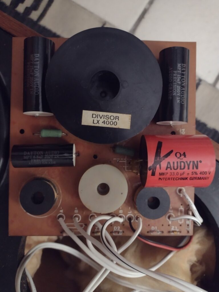
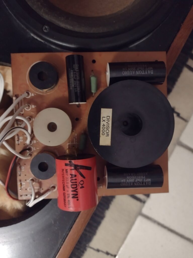
The speakers started to sound pretty close to each other. In the lower frequency range their difference is still noticeable. But we’re going in the right direction. After replacing the last two capacitors, we surely should step into another level for evaluating the performance of a stereo system. Soon I’ll cover that in a new section.
*** Page Under Construction ***
Do you have any more information on the low frequency drivers like the manufacturer and model number and driver specs?
Good afternoon.
Excellent work. I have a pair of Lando LY 18 speakers and I need the wiring diagram because the tweeter capacitors have exploded. The original tweeters were 8 Ohms and I will have to replace them with 4 Ohms because Lando no longer manufactures the originals.
Best regards