Servicing a Marantz 1150 console stereo amplifier
In this post I revisit the steps I’ve been through while servicing my Marantz model 1150 integrated amplifier. This amp changed the way I listen to music. But it was not at the first moment I turned it on. I’ll explain why.
Last updated on June 11th, 2024
The links below allows for a quick access to a subsection of this post:
- P800 Power Supply Board
- PE01 Tone Amplifier Board
- P400 EQ Amplifier Board
- P700 Power Amplifier Boards
- PH01 Filter Amp&Switch Board
- PN01 Relay Board
Warning: Please be aware of the risks when servicing any electrical equipment. You must make sure the electrical equipment and installations are maintained to prevent danger. You can get seriously injured. Repairs should only be carried out by someone who has the necessary skills, knowledge and experience to work safely. Always double check everything before plugging the power cord on and before putting your hands on, EVEN when they are not being powered.
How I got into this
I was looking for a real equipment to start a decent sound system for my own. I don’t mean a piece of plastic from the 90s, when the industry was lowering their budget with cheap material chassis, design and other general parts. I’m talking about those big beautiful consoles from the 70s. There are some marvelous models from several brands from that period. I focused on Marantz for a personal reason: my grandfather. He used to have a few modules and I might say he’s the one who inspired me to get into this. I remember how pretty the sound was coming from the bookshelves in his living room. If I needed a place to start from, that’s what I had in mind.
On day one
Of course I bought my Model 1150 Integrated Amplifier second handed from a guy in the Internet. Definitely a difficult thing to do since he was in a different brazilian state than me and I didn’t have the chance to personally check it out. Both sound and serigraphy matters when buying an old equipment. It’s also very important to chat with the seller and try to pull out of him any relevant information about previous repairing attempts (remember he’s trying to sell it).
Long story short: he didn’t want to ship it to me but I happened to have a friend in that town for that particular weekend. Luck, I guess. But a great deal of uncertainty about the deal there was either.
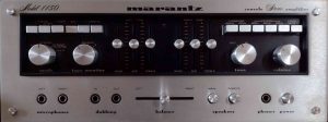
The first thing I did, after having a couple of beers to thank my friend for the whole inconvenience I made him pass, was turn that on! And… not very impressed. It sounded better than what I was using at home though. Time to open it and take a look closer.
First tip: Before changing things around, take pictures of everything in advance. In fact, many! And from different angles. Sometimes a wire breaks and gets loose, or you need to verify which transistor is there in that circuit board, or you’re simply investigating an issue… Pictures are your best friend and they are much more reliable than your memory!
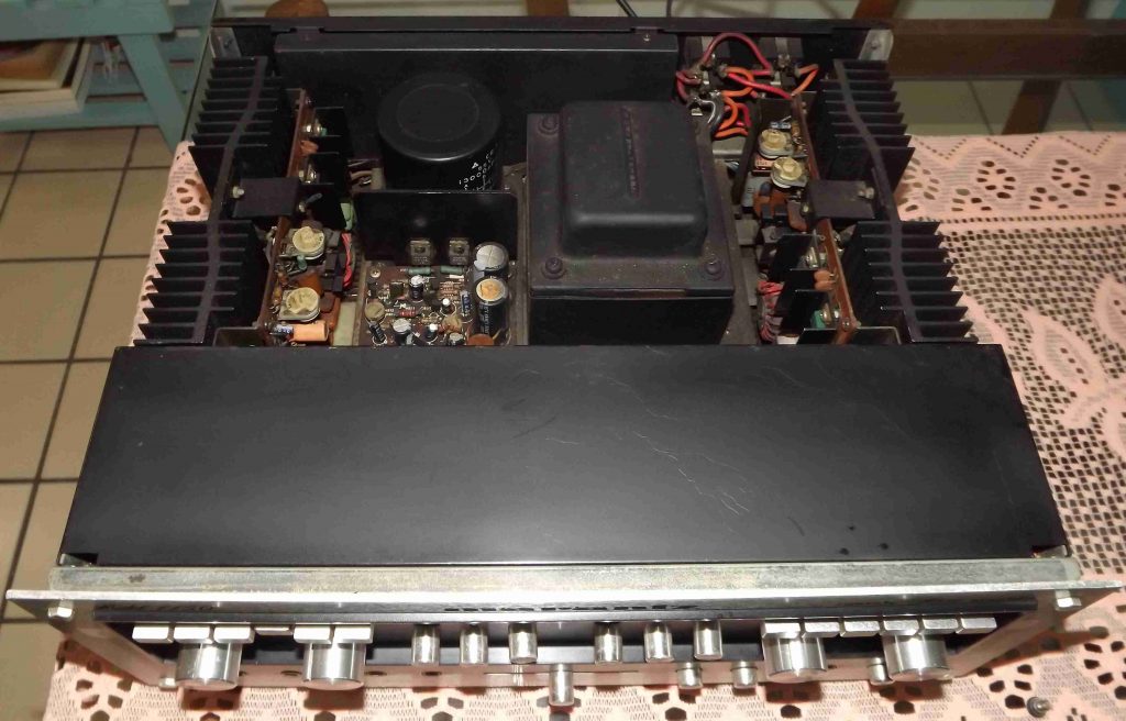
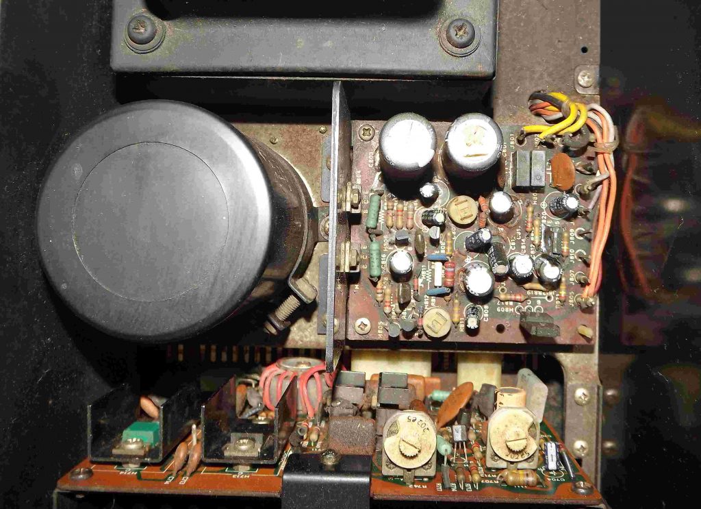
The P800 Power Supply Board
The audio amplifier console itself is composed by two, ideally identical, parallel circuits which stands for the left and right channels. It’s really two amplifiers in the same equipment. But they share one thing in common: the power supply. The DC voltages generated in this board supplies power to all other circuit boards in the equipment. Any instability in this block may cause spikes in the output signals, so we’ve got to check its health.
One great thing about this unit is the that it is mounted in modular boards. Each board can be removed, repaired or even replaced. We have to be very careful about cutting the wires and reconnecting them later. As we may need to do several steps while repairing them, I wouldn’t recommend soldering them each time you put the board back in. I managed to lengthen the wires and add a female crimp circular connector at them so its easier to take the board out for further inspections.
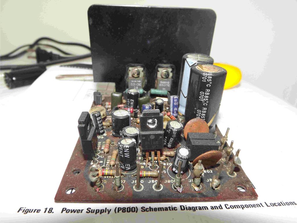
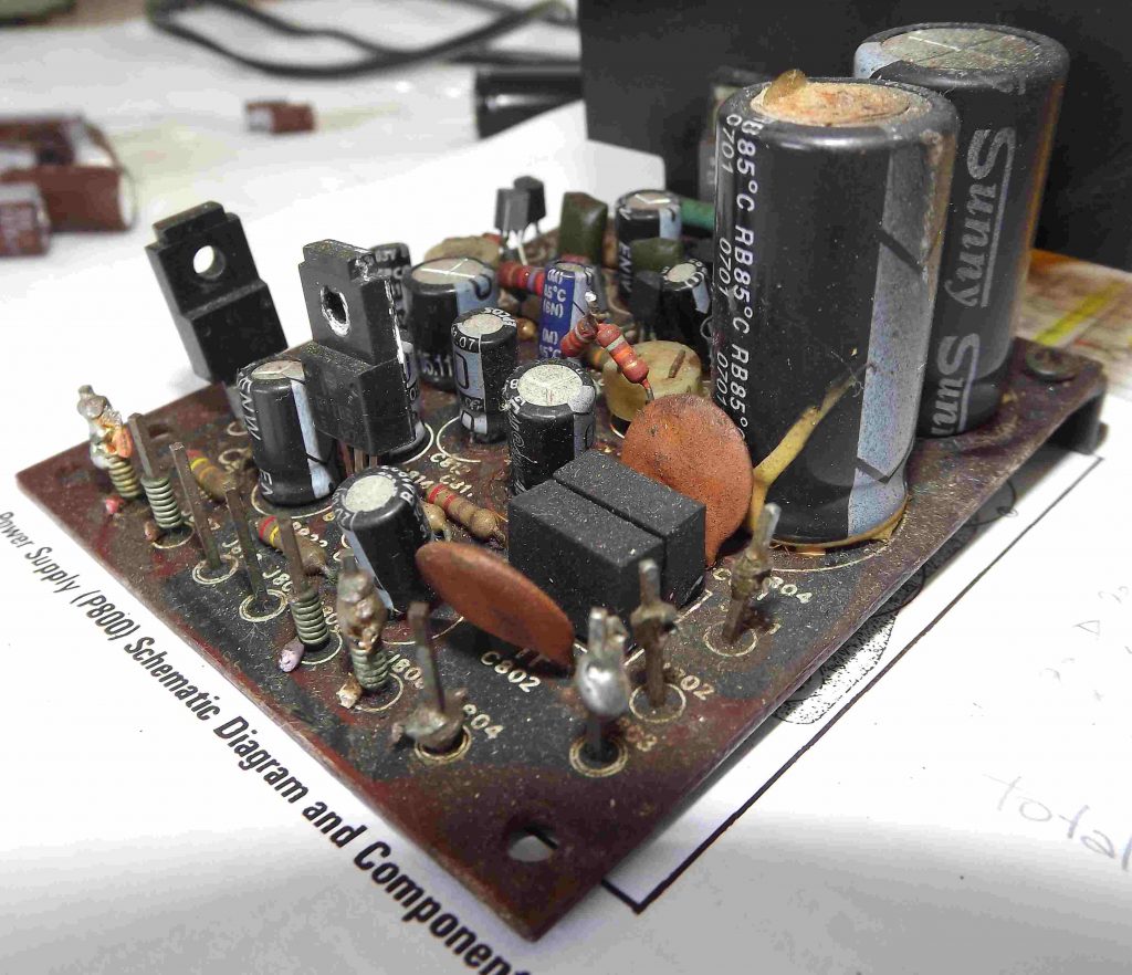
While giving the visual inspections on all boards, look for burnt places on the board due to excessive high currents, stewed capacitors, melted wires, or just something in suspicious condition. Anything that appears to me it was repaired or replaced is worth careful attention. Note, for example, a series resistors association right next to the big capacitor in the pictures above. The transistors H809 and H810 also didn’t match with their references in the parts list. For sure something went wrong, but luckily the unit was in a working state. Otherwise, we would have to identify the causes of failure first and try to fix them.
A very important thing came to light after searching over the web. Even if everything appears to be fine to your eyes, some components may get way off their specifications or stop working completely. Those components are the non-solid electrolytic capacitors (or wet capacitors). An amplifier, or any equipment in general, should need servicing for replacing the electrolytic capacitors (also known as Recap) after a few decades or so. In a 40 years power amplifier it is a must-do task. Fortunately in those days the equipments were sold along with its service manual guide with schematics, parts list, components reference and disassembling steps. Also they were built with big discrete components, instead of tiny surface-mounted devices like nowadays. But the thing is: some parts may be hard-to-find, discontinued, obscure, obsolete components. Most of them have an equivalent replacement but some time-consuming researching process is required. But that’s part of the job! Needless to say, they are not being made anymore. They belong to another era, so to speak. As time goes by, some of those units goes to the garbage, some get lost in someone’s basement, some are disassembled for other purposes. The ones the survives are getting rather rare today. So having any of these amplifiers from the 60s and 70s in your arms is already for few. Do not miss the chance of getting the real sound out of them. Buy audio grade components for it. Now, that leads to another issue worth of commenting: how much is it gonna cost me? After a quick search, you’ll find out a single capacitor can cost from half to tens US dollars. Of course you should go as deep as you can without getting drowned.
From the Parts List session of the Service Manual, I made a list of all the electrolytic capacitors and ordered them from PartsConnexion. I decided to go with the Elna RFS Silmic II (pretty much all of them) and the Elna ROA Cerafine in the power supply rectifier’s filter (C803 and C804) and on the relay board (CN05).
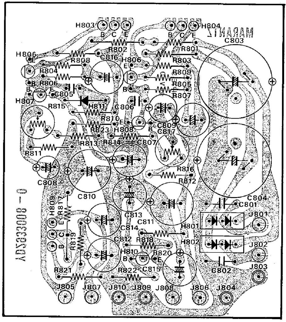
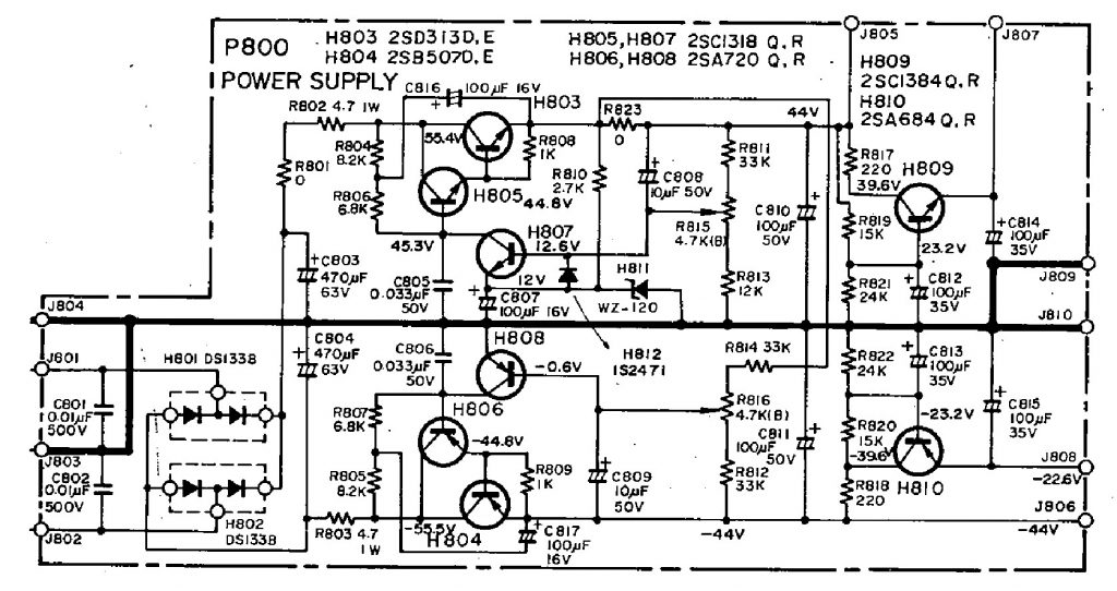
P800 – Replacing the electrolytic capacitors (13 caps)
While replacing the caps, pay attention to the values found in each position and to the polarity orientations as well. Some misleadings between the schematics and drawings on boards may occur and they are not that rare. Remember someone else probably worked on it before you, then double check everything!
| Schematics Board | Board Reference | Replacement | Quantity | Notes |
| 470uF, 63V 220uF, 200V | C803, C804 | 470uF, 63V Elna Cerafine | 2 | Replaced |
| 10uF, 50V 10uF, 63V | C808, C809 | 10uF, 50V Elna Silmic II | 2 | Replaced |
| 100uF, 50V 100uF, 63V | C810, C811 | 100uF, 50V Elna Silmic II | 2 | Replaced |
| 100uF, 35V 100uF, 35/35/50/63V | C812, C813, C814, C815 | 100uF, 35V Elna Silmic II | 4 | Replaced |
| 100uF, 16V 100uF, 16/16/63V | C807, C816, C817 | 100uF, 25V Elna Silmic II | 3 | Replaced |
Clearly this board was previously serviced without much care and with cheap general purpose capacitors. Let me handle this for now on.
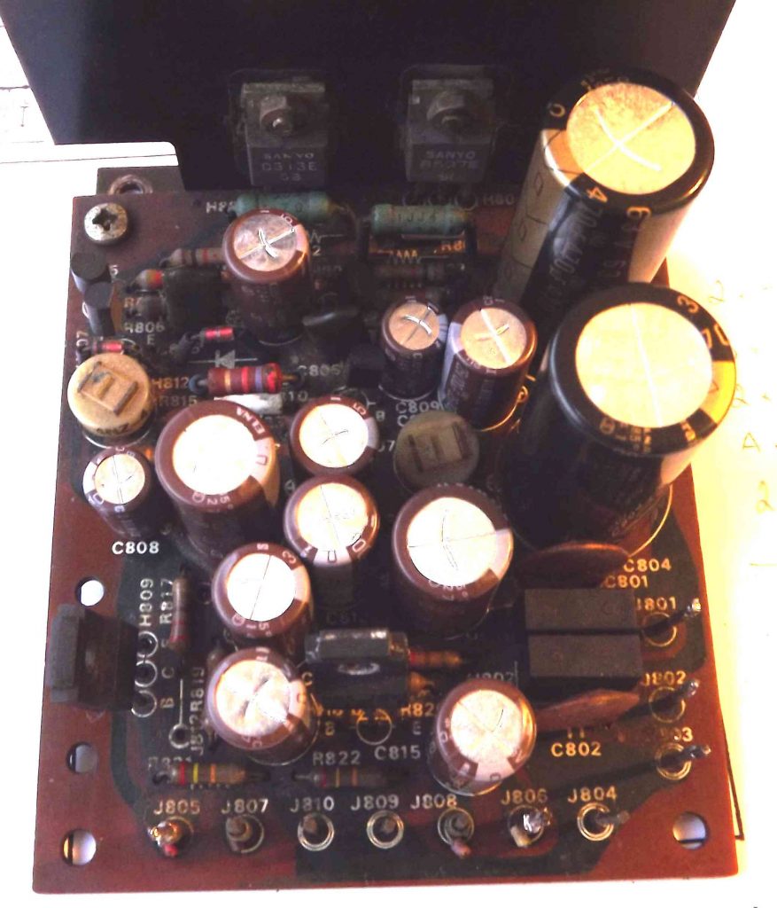
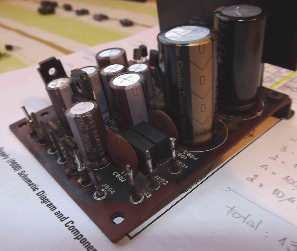
Much better now… but we’re just warming up. Now it’s time to check the voltages, adjust the trimpots and, if everything is as should, put the power supply back in and try the amplifier. While servicing, I rather taking steps slowly. Never make too much changes without hearing the overall results. You and your equipment are getting to know each other. Be nice and easy.
P800 – Checking the transistors (8 units)
Not only the capacitors in this board needed attention but the transistors health must be checked. Some transistors differs from the listed and I have the intention of replacing them back to the original reference parts as much as possible. That job may take some time. Differently from the capacitors, which I ordered them all from the same supplier, very unlikely the transistors can be found in one single supplier. So it’s a task of searching each of them every local shop I go.
When you’re working with the board off the power, check if the BJT terminals are not in short and verify if their PN junctions are alright. With the power on, carefully check the voltages. If the base-emitter bias voltage is correct, you can trust it for now.
It toke me some time to solve some sporadic pops I was hearing. I found out the transistor H804 was faulty and replaced it with a TIP42C that I had at home. It’s doing fine now. I also happened to find transistors H809 and H810 as the original listed parts and replaced them. H805, H807 and H806, H808 could not be found yet but they are doing their jobs.
| Schematics Board | Board Reference | Replacement | Quantity | Notes |
| 2SD313 D, E | H803 | Original | 1 | Good |
| 2SB507 D, E | H804 | TIP42C | 1 | Damaged, replaced |
| 2SC1318 Q, R BC337 | H805, H807 | – | 2 | Good, not replaced |
| 2SA720 Q, R BC640C | H806, H808 | – | 2 | Good, not replaced |
| 2SC1384 Q, R 2SD1944 K | H809 | 2SC1384 R | 1 | Good, but replaced by original |
| 2SA684 Q, R 2SB1185 E | H810 | 2SA684 R | 1 | Good, but replaced by original |
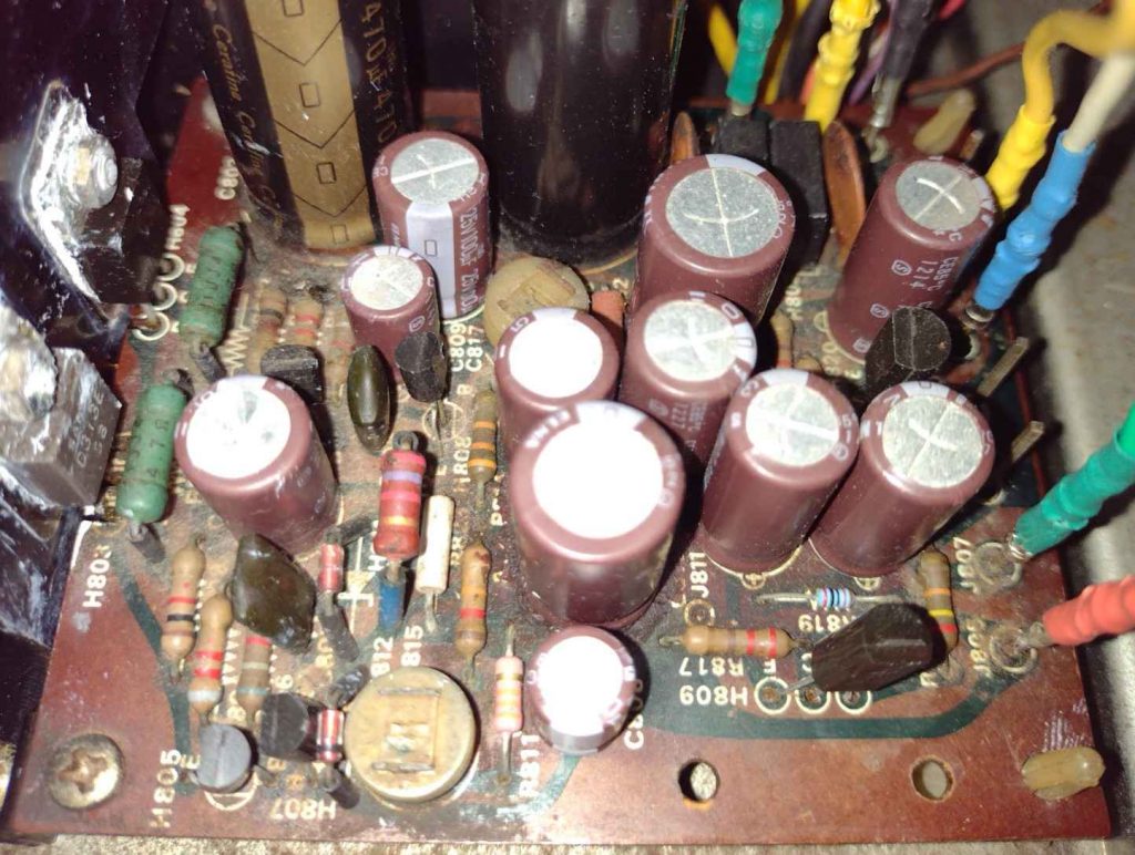
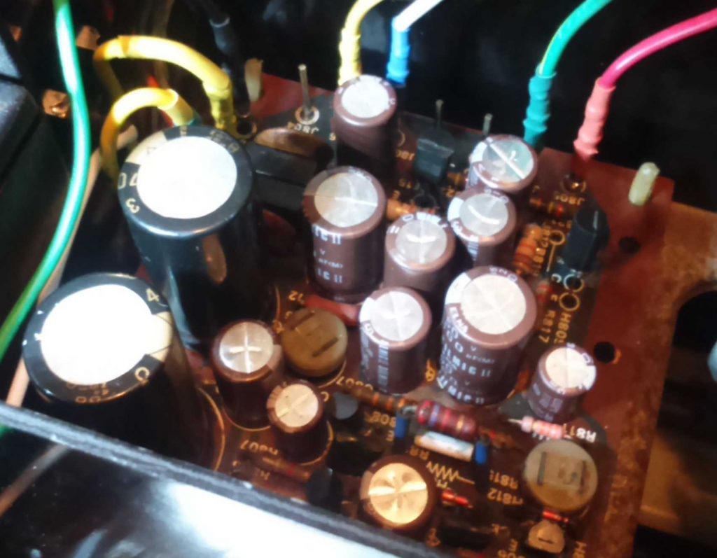
This board has two trimmer potentiometers for adjusting the positive and negative voltage sources. They should provide +44V and -44V respectively. From that voltages the circuit generates secondary voltage sources of 22.6V and -22.6V by dividing the voltages and buffering them by means of transistors H809 and H810. In order to adjust those secondary sources we can change the values of R819 and R820. In my case, I had to change the resistor R819 from 15k to 20k for adjusting a symmetrical voltage source around 22.6V.
Replacing the Main Reservoir Capacitors
After every day of servicing, I always spend a few days listening to a some records to perform an ear-test. It was doing fine until one day I woke up with a 60Hz humming coming out of it. Time to investigate. So I unplugged the input source cable and made sure it wasn’t coming from a poor electrical contact in the input. Then I reconnected it and played some sound and checked the channels. Both were there but they couldn’t handle the lower frequency range and, by turning the volume up, it was getting more pronounced. At that moment I knew it should be power supply related. It could be in the P800 board itself, which I was working on the day before, so I checked the board output voltages and they were fine. Or it could be the Main Reservoir Capacitors which are responsible for storaging DC voltage to supply the output power stage of the amplifier. Those caps are generally large and must handle the high electrical current surge while feeding the output speakers. By checking the voltages It confirmed the positive terminal was way below from expected 45.8V. As predicted for a wet electrolytic capacitor, its dielectric insulator had been drying out for the last four decades and it was finally saying goodbye from its duty. This did not affected the power supply board voltages because it comes from different transformer wirings.
In this model, those capacitors come together in one single cylindrical three pin package and I couldn’t find a brand new replacement in my searches. What I found to be a good choice was to buy two capacitors and connect one’s positive terminal to the other’s negative terminal. This junction should be the ground terminal and the two others being the respective positive and negative terminals. The major concern then is where it would fit. It should not be left loose inside the console and it should avoid any electrical contact to its terminals by any chance.
I ended up buying a pair of Nichicon Gold Tune caps as they appeared to be a great option for that purpose and managed to find a place somehow once they arrived. It happened to fit very well alongside the transformer, between the power supply board and the right output channel as shown below. There are two concerns around this. First, the transformer normally gets quite warm and heats its surroundings. And second, it’s hard to find a way to attach them to the chassis. As a workaround, I’ve used EVA foam sheets for improving thermal insulation and filling the spaces around to prevent them from being displaced. Though it’s far from ideal, I’ve been running it like this for some time and didn’t have any issues.
How did it sound afterwards? I can tell It just marks the starting point for this whole servicing journey. Do not under estimate the role of these reservoir capacitors. Just think about it. By the end of the signal path throughout the whole equipment, it gets to a pair of bipolar transistors which act as a current source which pulls energy storaged in those capacitors to feed the speaker coils. It’s sort of saying the sound that actually is being reproduced by the loudspeaker system comes from energy in those caps! Hence, why don’t we say they are signal path capacitors?
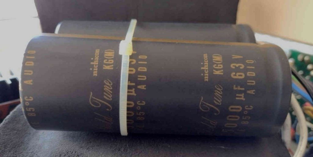
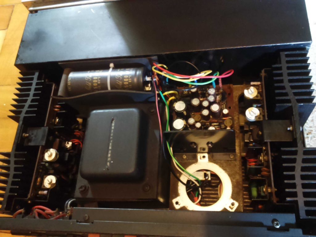
| Schematics | Board Reference | Replacement | Quantity | Notes |
| 13000uF x2, 55V | C010 | 13000uF, 63V Nichicon Gold Tune | 2 | Replaced |
The PE01 Tone Amplifier
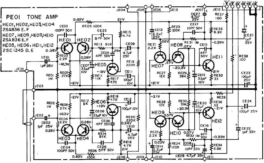
The Tone Control in the front panel is implemented by two boards. The PE01 Tone Amplifier, which is a flat frequency response amplifier circuit, and PF01 Tone Control Volume, which is a feedback loop and contains the potentiometers for altering the amplifier’s frequency response. The Tone switch in the front panel allows to switch between the adjustable filters feedback or a fixed resistive feedback (for a flat frequency response). The Tone Control is very useful to correct some room interference such as sound absorption and reverberation. It’s highly desirable to have hi-fi loudspeakers and to choose an appropriate room for the audio system. Now remember: Its goal is to be as transparent as possible. Hearing music on a hi-fi audio equipment is sort of a travel in time. You can feel how albums were recorded and mixed around the decades. I always set the tone controls at flat. When no further improvement in the sound quality can be made by modifying the room acoustics, the effect of the tone controls can then be tried. If it’s still at flat, switching it off is preferable (and even flatter).
The amplifier board holds 18 electrolytic capacitors, some of them in the signal path and, as I was getting more and more excited about the recapping results, I felt its time has come.
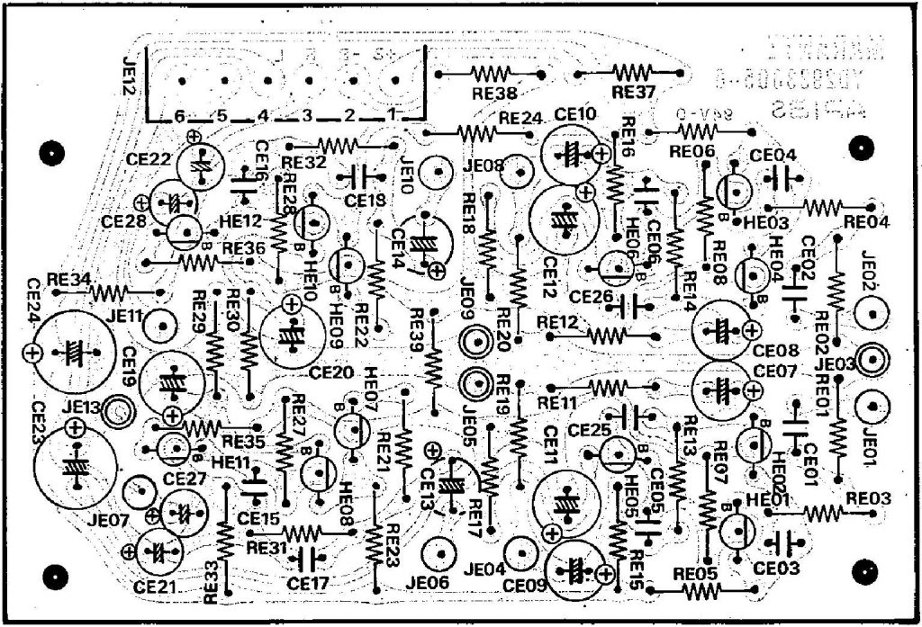
PE01 – Replacing the electrolytic capacitors (18 caps)
All electrolytic capacitors were replaced. Most of them were tantalum caps. While replacing CE19 and CE20, there were 47uF caps instead of 33uF as listed in the Service Manual (both schematics and parts list). A larger capacitance is allowed where they are located and they were Elna capacitors, so I kept them 47uF for having the evidence of them being from factory.
| Schematics Board | Board Reference | Replacement | Quantity | Notes |
| 1uF, 25V (Ta) | CE01, CE02 | 1uF, 50V, Bipolar Nichicon | 2 | Replaced |
| 33uF, 10V (Ta) | CE07, CE08 | 33uF, 25V Elna Silmic II | 2 | Replaced |
| 4.7uF, 25V (Ta) | CE09, CE10, CE27, CE28 | 4.7uF, 25V Elna Silmic II | 4 | Replaced |
| 100uF, 10V 100uF, 35V | CE11, CE12 | 100uF, 25V Elna Silmic II | 2 | Replaced |
| 2.2uF, 25V (Ta) | CE13, CE14 | 2.2uF, 50V Elna Silmic II | 2 | Replaced |
| 33uF, 10V 47uF, 10V | CE19, CE20 | 47uF, 16V Elna Silmic II | 2 | Replaced for 47uF as found |
| 1uF, 35V (Ta) | CE21, CE22 | 1uF, 50V Elna Silmic II | 2 | Replaced |
| 100uF, 25V 100uF, 35V | CE23, CE24 | 100uF, 35V Elna Silmic II | 2 | Replaced |
PE01 – Checking the transistors (12 units)
No issues found in the transistors.
| Schematics | Board Reference | Replacement | Quantity | Notes |
| 2SA836 E, F | HE01, HE02, HE03, HE04, HE07, HE08, HE09, HE10 | Original | 8 | Good |
| 2SC1345 D, E | HE05, HE06, HE11, HE12 | Original | 4 | Good |
The P400 EQ Amp
This board is responsible for performing the RIAA equalization. In other words, it boosts the lower and attenuates the higher frequencies according to a specific standard curve. It’s also known as the phono preamplifier and either the phono and the microphones input signals can go through it. Only if your turntable does not have a built-in preamplifier stage you’re supposed to use the phono input. If it does have one, you might plug it to the aux input. Here is an interesting discussion about RIAA curve.
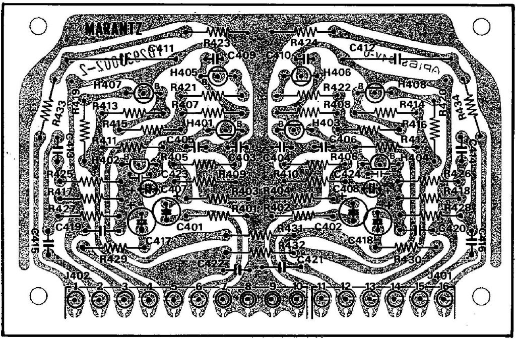
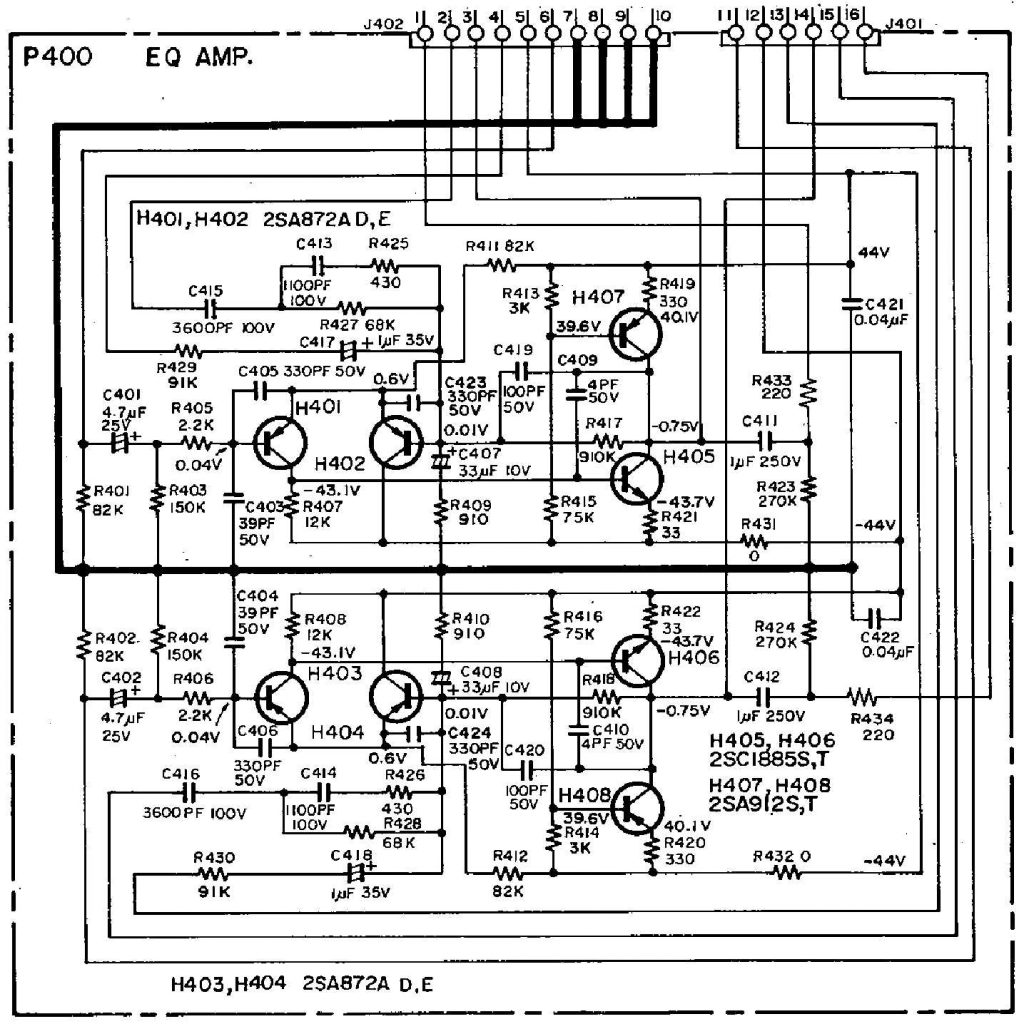
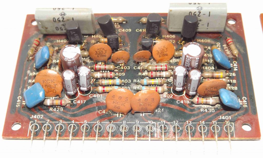
No issues where found in this board. Just replaced the tantalum electrolytic for the Elna aluminum electrolytic capacitors.
P400 – Replacing the electrolytic capacitors (6 caps)
| Schematics | Board Reference | Replacement | Quantity | Notes |
| 4.7uF, 25V (Ta) | C401, C402 | 4.7uF, 25V Elna Silmic II | 2 | Replaced |
| 33uF, 10V (Ta) | C407, C408 | 33uF, 25V Elna Silmic II | 2 | Replaced |
| 1uF, 35V (Ta) | C417, C418 | 1uF, 50V Elna Silmic II | 2 | Replaced |
P400 – Checking the transistors (8 units)
| Original Schematics | Board Reference | Replacement | Quantity | Notes |
| 2SA872A D, E | H401, H402, H403, H404 | Original | 4 | Good |
| 2SC1885 S, T | H405, H406 | Original | 2 | Good |
| 2SA912 S, T | H407, H408 | Original | 2 | Good |
The P700 Power Amplifier Boards
The P700 boards are two separated boards, one for each channel, with the same component labels. There are two trimpots R741 and R742 for adjustment of the DC Offset Voltage and the Idling Current adjustment, respectively. After verifying the Power Supply Board, it’s a good practice to perform the Power Amplifier adjustments on both channels.
Tip 1: Use Alligator Clip type leads for proper measurement
Tip 2: Adjust these two parameters on one channel first then move to the other channel. Perform several interleaved measurements of both parameters until they seem stable.
Tip 3: JN04, JN05 and JN10 (Ground) are actually reachable at the Relay Board
DC Offset Adjustment
Connect the voltmeter to JN04 (left channel) and JN10 (or choose a good Ground potential) and adjust R741 until the meter indication reaches 0mV (or between -5mV and 5mV). Do the same for the right channel on JN05 test point.
Adjusting the Idling Current
Connect the voltmeter to J701 and J702 on the left channel and adjust R742 until the meter reads 10mV. Do the same on the right channel.
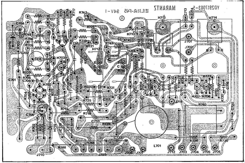
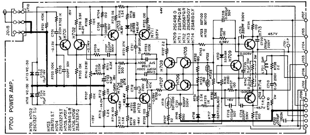
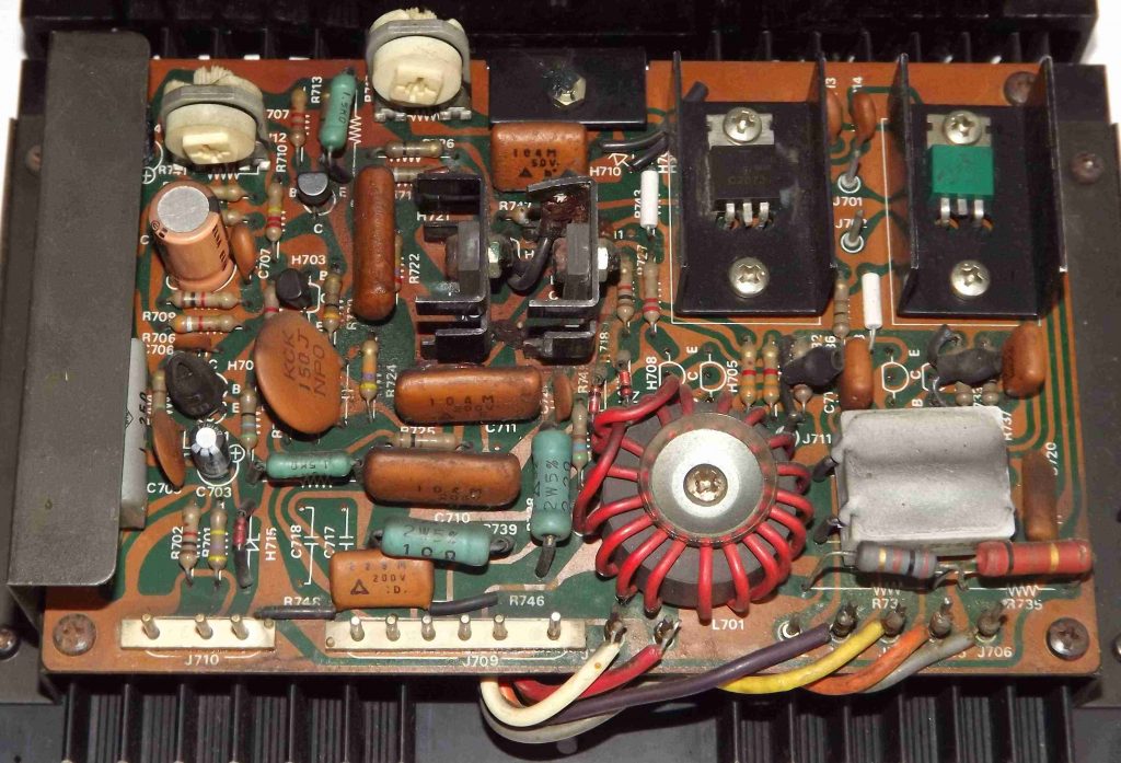
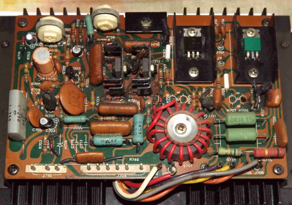
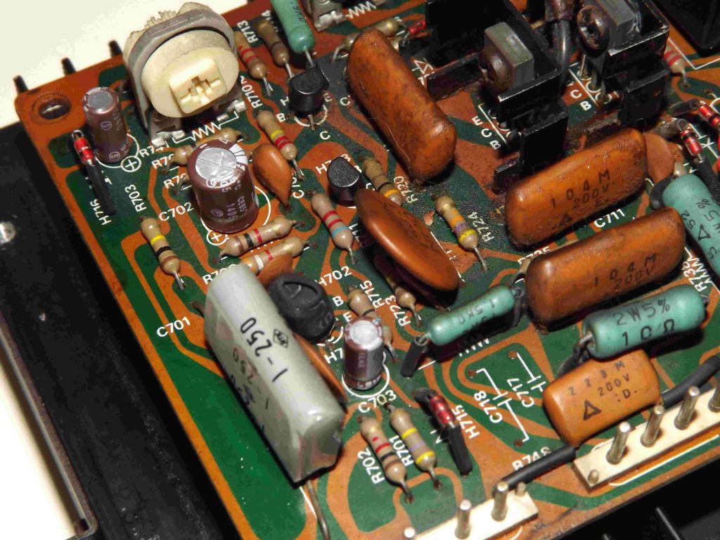
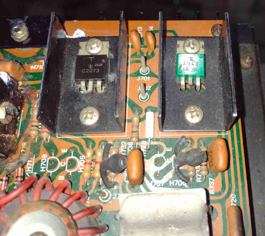
Continuing with the visual inspections, as can be clearly observed in the pictures below, some components were replaced like R740 (on the right) and transistors H705, H706, H707 and H708 were removed without being replaced (on both channels). There are some burnt places indicating over current. Capacitors C717 and C718 are missing but were not listed in the service manual either (so let it still).
The R740 is a block with two thermally coupled 0.2 ohm resistors. It had been replaced for two 0.33 ohm resistors. I didn’t spend to much time looking for the original part but surely replaced them by two 0.22 ohm resistors. For the future, I’m considering replacing it on the other board as well for sake of channels symmetry.
P700 – Replacing the electrolytic capacitors (3 caps per board)
The orange electrolytics in the pictures above are Elna 47uF capacitors. Seems like they survived the previous servicing! Let them rest in peace now. All of them have been properly replaced.
| Schematics Board | Board Reference | Replacement | Quantity | Notes |
| 47uF, 16V | C702 | 47uF, 16V Elna Silmic II | 1 | Replaced |
| 10uF, 16V 10uF, 16/16V (right) 10uF, 63/63V (left) | C703, C704 | 10uF, 50V Elna Silmic II | 2 | Replaced |
P700 – Checking the transistors (15 per board)
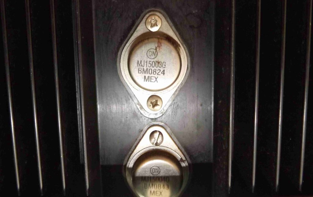
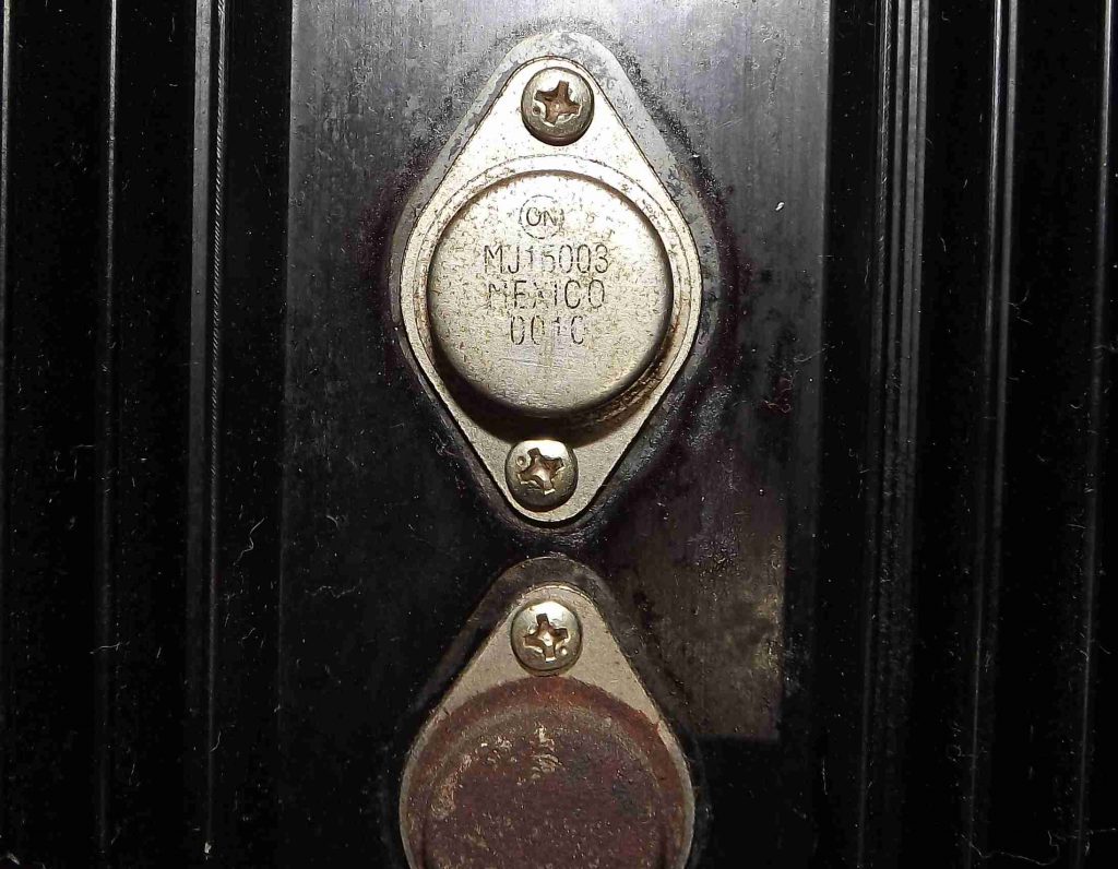
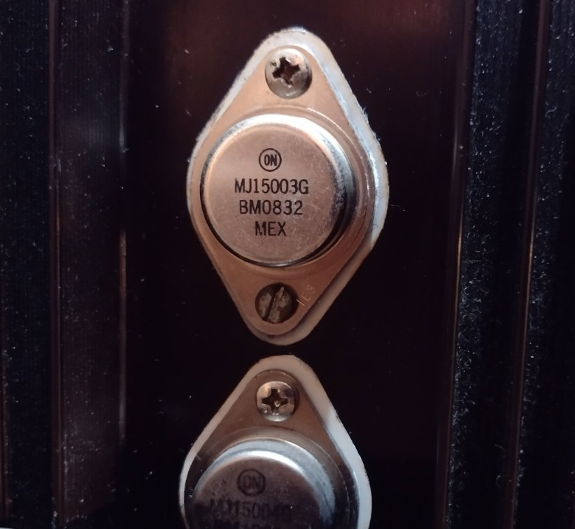
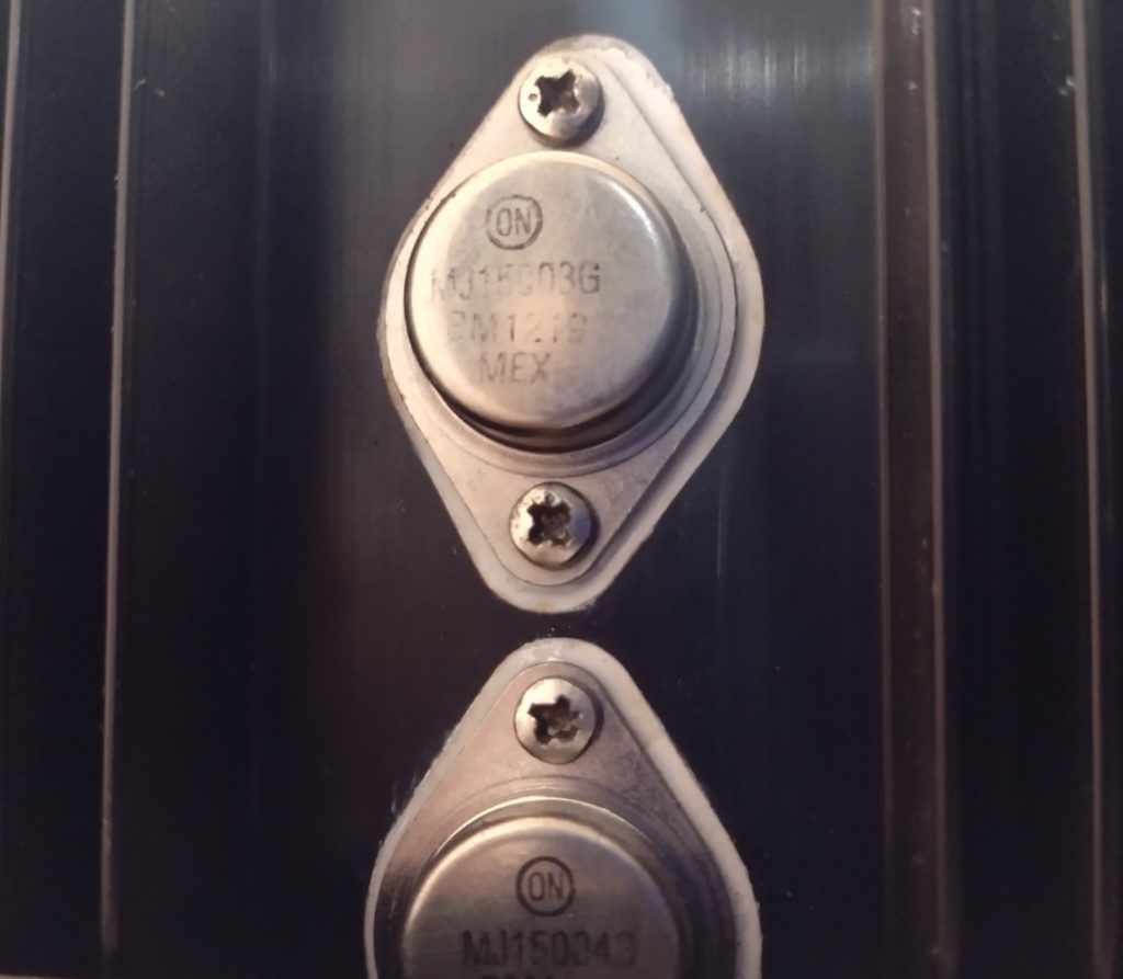
After replacing the capacitors and performing the necessary adjustments on both boards, I’ve checked if every transistor was fine and whether any of them was previously replaced. All four output power transistors had been replaced by MJ15003(G) and MJ15004(G) but were in bad visual condition. Also both power driver stage transistors H713 and H714 didn’t match with the parts list. At first, I didn’t replace anything. A few months later, while I was doing some tests, I accidentally touched an input cable hot connection and one of the channels went silent. Fortunately, replacing all four H002-H005 output power transistors fixed the issue.
Currently, I am studying and looking for replacing the transistors from the driver stage H713 and H714. I also bought H705-H708 transistors but I’m still being precautious about them. This section must have some updates soon!
| Schematics Board | Board Reference | Replacement | Quantity | Notes |
| 2SC1327 T, U | H701, H702 | Original | 2 | Good |
| 2SA721 S, T | H703 | Original | 1 | Good |
| 2SC1327 S, T | H704 | Original | 1 | Good |
| 2SC945 Q, R | H705, H707 | Pending | 2 | Missing |
| 2SA733 P, Q | H706, H708 | Pending | 2 | Missing |
| 2SC496 O | H709 | Original | 1 | Good |
| 2SA794 Q, R | H711 | Original | 1 | Good |
| 2SC1567 Q, R | H712 | Original | 1 | Good |
| 2SC1625 O, Y 2SC2073 | H713 | – | 1 | Good, not replaced |
| 2SA815 O, Y 2SA940 | H714 | – | 1 | Good, not replaced |
| S40442 MJ15004 G | H002 (H004) | MJ15004 G | 1 | Replaced |
| S40443 MJ15003 G | H003 (H005) | MJ15003 G | 1 | Replaced |
The PH01 Filter Amplifier and Switch Board
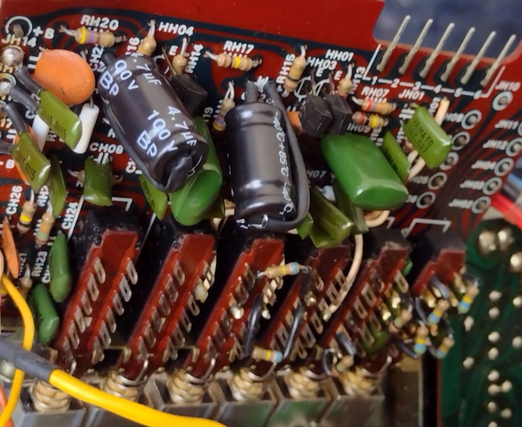
On this board I noticed the capacitors CH21 and CH22 were listed as film capacitors and appears as being electrolytic capacitors in the schematics and in the PCB below. For that reason I didn’t order any 4.7uF rating 35V or higher. Interestingly there were a tantalum and a cylindrical bipolar (which are both electrolytic) capacitors on the board. We can trust the tantalum to be original, as seen in many other places around the equipment, but very unlikely the other one has been replaced due to an issue (though early failures can happen).
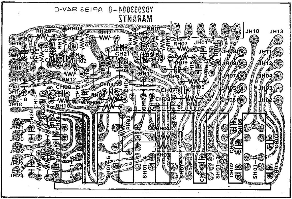
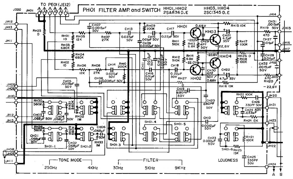
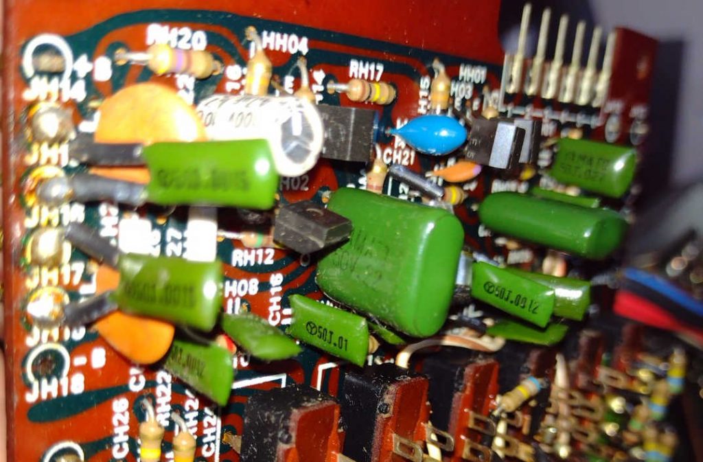
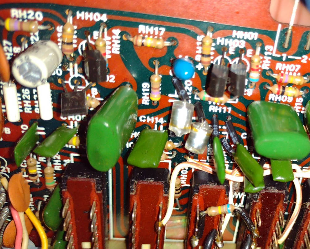
There is a great discussion about capacitor types in audio signal path here. I admit I came across this topic after replacing both for bipolar caps. Although I believe the tantalum cap to be the original one, I have no doubt replacing both by bipolar caps was a great choice. But I’ll consider replacing them for film caps, or Elna Silmic II like the others, if I have nothing else to worry about.
PH01 – Replacing all the electrolytic capacitors (2 units)
| Schematics Board | Board Reference | Replacement | Quantity | Notes |
| 4.7uF, 35V (Ta) 4.7uF, 35V (Ta) 4.7uF, 100V | CH21, CH22 | 4.7uF, 100V BP | 2 | Good, but both replaced |
PH01 – Checking the transistors (4 units)
| Original Schematics | Board Reference | Replacement | Quantity | Notes |
| 2SA836 D, E | HH01, HH02 | Original | 2 | Good |
| 2SC1345 D, E | HH03, HH04 | Original | 2 | Good |
The PN01 Relay Board
The Relay Board, commonly referred to as the Speaker Protection Circuit, is a mechanism mainly intended to prevent the loudspeakers, or the power stage itself, from being damaged due to an abnormal event. This circuit block also ensures a few seconds delay before releasing the signal to the output speakers during the power up transient period.
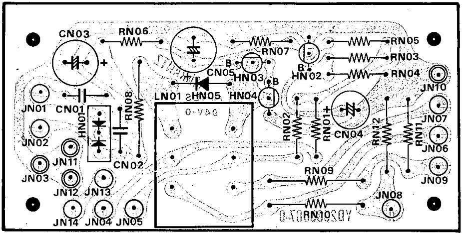
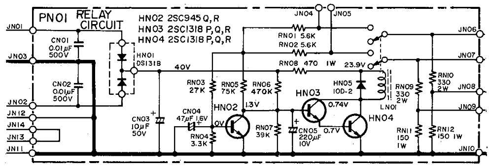
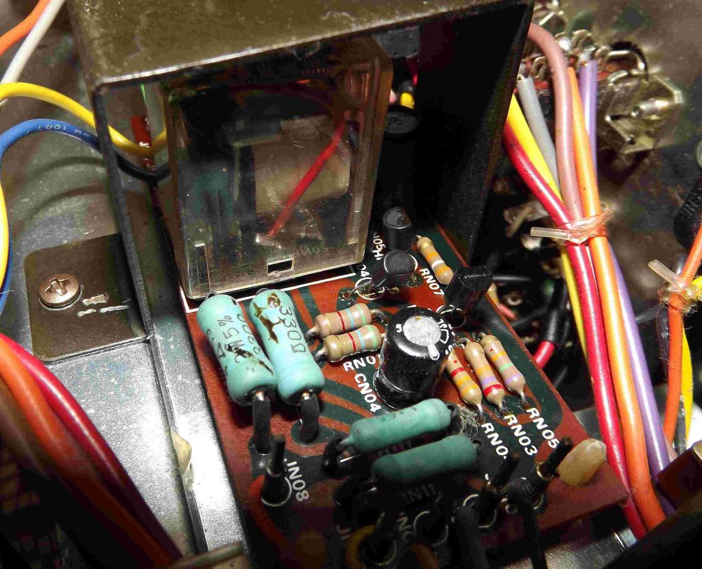
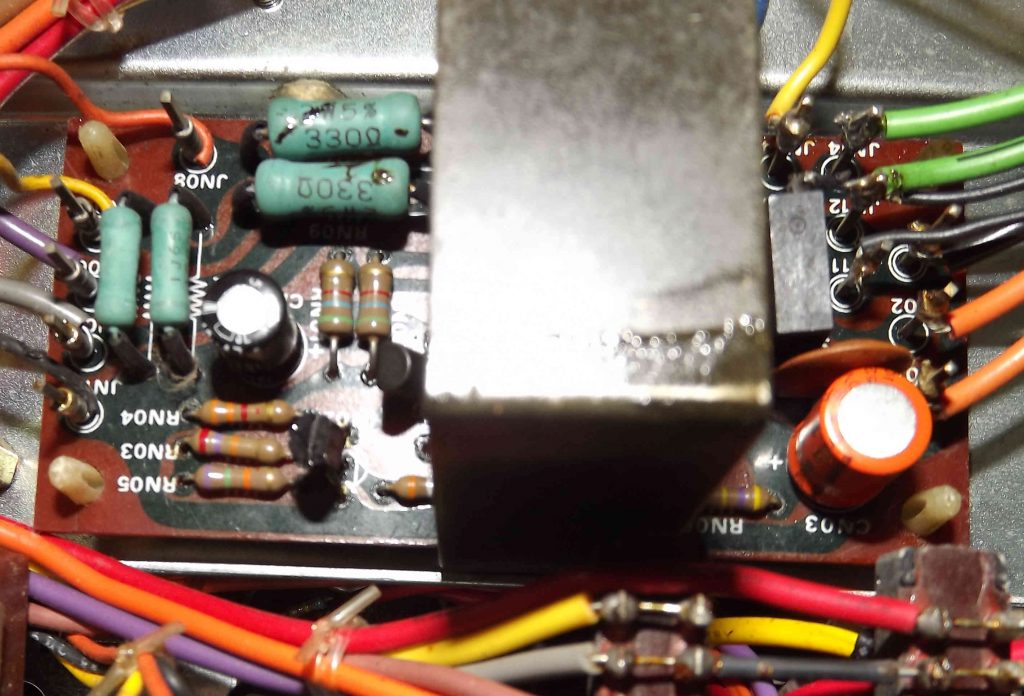
The output relay is a DPDT (Double Pole Double Throw) switch which releases the signal to the output while its coil is being energized and disconnects the output otherwise. For that reason, it may be responsible for some output signal loss. It’s important to remove any oxidation from its electrical contacts. Some people use a fine grain sandpaper. I rather use isopropyl alcohol for cleaning any kind of electrical contacts.
PN01 – Replacing the electrolytic capacitors (3 units)
| Schematics Board | Board Reference | Replacement | Quantity | Notes |
| 10uF, 50V 10uF, 100V | CN03 | 10uF, 50V Elna Silmic II | 1 | Replaced |
| 47uF, 16V | CN04 | 47uF, 16V Elna Silmic II | 1 | Replaced |
| 220uF, 10V | CN05 | 220uF, 10V Elna Cerafine | 1 | Replaced |
PN01 – Checking the transistors (3 units)
| Schematics | Board Reference | Replacement | Quantity | Notes |
| 2SC945 Q, R | HN02 | Original | 1 | Good |
| 2SC1318 P, Q, R | HN03, HN04 | Original | 2 | Good |
Quick Guide
Alternative Replacement Parts for transistors
The table below is a compilation of alternatives parts for the transistors in Model 1150 found during my researches. I haven’t checked the datasheets of every item on this list, so I can not assure you this replacements are correct. I suggest you to double check every information you find over the Internet before replacing in your unit. If you have any suggestion or correction about these parts, please comment below. Thank you!
| Schematics | Board Reference | Alternatives | Quantity |
| 2SD313 D, E | H803 | BD587 2N5298 NTE152 BD241A | 1 |
| 2SB507 D, E | H804 | BD590 2N6126 NTE153 BD178 | 1 |
| 2SC1318 Q, R | H805, H807, HN03, HN04 | BCW36 2N4410 NTE128 | 4 |
| 2SA720 Q, R | H806, H808 | BCW37 2N2904 NTE290A BC327 | 2 |
| 2SC1384 Q, R | H809 | BD135 2SD1944 | 1 |
| 2SA684 Q, R | H810 | BD136 2SB1185 | 1 |
| 2SC1327 T, U | H701, H702 | BC547 NTE199 BC182L 2N5210 | 4 |
| 2SA721 T | H703 | BC212L BC559 2N4061 | 2 |
| 2SC1327 S | H704 | BC547 NTE199 BC182L 2N5210 | 2 |
| 2SC945 Q, R | H705, H707, HN02 | 2SC1815 BC407B BC182L 2N3710 BC167B | 5 |
| 2SA733 P, Q | H706, H708 | BC257 NTE290 BC212L 2N4061 BC557 | 4 |
| 2SC496 O | H709 | BD135 NTE295 BD169 2N4923 | 2 |
| 2SA794 Q, R | H711 | BD140 NTE211 2N5415S | 2 |
| 2SC1567 Q, R | H712 | BF457 NTE373 2N5100 | 2 |
| 2SC1625 O, Y | H713 | BD239C 2N5241 2SC2073 | 2 |
| 2SA815 O, Y | H714 | BD940 2N6180 2SA940 | 2 |
| S40442 | H002 (H004) | MJ15004 G | 2 |
| S40443 | H003 (H005) | MJ15003 G | 2 |
| 2SA836 E, F | HE01, HE02, HE03, HE04, HE07, HE08, HE09, HE10 | NTE234 BSW24 2N3494 | 8 |
| 2SA836 D, E | HH01, HH02 | NTE234 BSW24 2N3494 | 2 |
| 2SC1345 D, E | HE05, HE06, HE11, HE12, HH03, HH04 | NTE199 BC414 | 6 |
| 2SA872A D | H401, H402, H403, H404 | 2SA893 NTE288 BF435-2N3930 | 4 |
| 2SC1885 S | H405, H406 | 2SC589 NTE399 KSC2310 | 2 |
| 2SA912 S | H407, H408 | 2SA712 2N5415 BF423 | 2 |
Thanks for reading!

This was an interesting read to me because I own a Marantz 1150 that I haven’t used in probably 20+ years due to its right channel making a staticy sound after listening to it for some time, that goes away after turning it off/on again, but it seems I recall there were times when that staticy sound wouldn’t go away after cycling off/on again. Anyway, your story has given me motivation to re-cap mine, and figure out the staticy issue. I’ve some questions for you. How does your 1150 sound after re-capping compared to before you re-capped it? Where did you connect your leads for measuring voltage while adjusting the R741 and R742 trimpots on the P800 board? On the amplifier boards, I understood where to connect the leads when adjusting R742, but where do I connect them for adjusting R741, and what should the reading be after adjusting R741? Thank you for writing this nice webpage. I’m handy at desoldering old parts and soldering in new parts, and I intend to get my old 1150 going again now by replacing its capacitors first.
Hi, John! Thank you so much for reading and leaving your comment!
As I mentioned somewhere, I took my time during the whole process doing small changes at a time. I wanted to make sure I wasn’t messing anything up. Imagine changing all of them at once to find out something went wrong god-knows-where… So I did many hearing inspections along the way.
Did I feel any difference right away? At the moment you wish so much to hear a sound improvement that you end up hearing it, or getting frustrated by not hearing any difference at all! Of course there was. But, unless there was something really out-of-spec, it may take time by hearing some records you’re very familiar with for pointing out those improvements. I rather not putting anything into words like punchy or detailed… But soon there will be a post about some electrical characterization I am working on, ok?
You mean on the P700 Output Power Amplifier boards, right? Check out the Tip 3: JN04, JN05 and JN10 (Ground) are actually reachable at the Relay Board. JN04 for the left channel and JN05 for the right channel and they should be very close to 0V (or a few milivolts).
Well, let me know about your progress and feel comfortable to reach out if you have any questions.
Thank you for your reply! It is sensible to make repairs one circuit board at-a-time, followed by retesting to make sure your repair works correctly as you go along, as you’ve done. I will do the same when I get into replacing my capacitors.
I miswrote. It was actually the R815 and R816 trimpots on the P800 board that I wondered where you connect your voltmeter to test. I understand that the outputs are supposed to be +44V and -44V at connections J805 and J806 respectively and +22.6V and -22.6V at J807 and J808, but; am I understanding correctly that turning one trimpot adjusts the +44V while turning the other trimpot adjusts the -44V, then you replace resistors R819 and R820 with ones having the correct resistance to adjust the +22.6 and -22.6 voltages?
That’s OK if you’d rather not describe the difference you hear before-and-after changing the capacitors. I wondered if it were a “night and day” difference you noticed. I’ve only ever changed capacitors in speaker’s crossovers, and I’ve noticed quite a difference in sound before-and-after when changing those. I wondered if changing the capacitors in an amplifier makes a similar difference in the sound quality.
Thank you for your willingness to answer any questions. I may ask you for advice if I need it along the way. My next step is to order myself some capacitors.
About the P800 board, yes. You’ve got that correctly. The only way is to adjust transistors H809 and H810 biasing to adjust the 22.6V. As I needed to lower the output voltage, I’ve decided to increase R819, rather than to decrease R821, for a lower V_BE.
Alright, that “night and day” difference I can tell you. It’s not even close to the effect on speaker’s crossovers. Again, unless any capacitor is way off it’s specification. Otherwise, don’t expect a similar impact.
In advance, those 13000uF reservoir capacitors really make a difference in my opinion. And they suffer a lot of stress over time. Those are mandatory. But pay attention to their size dimensions if you do not find the exact replacement, and think how you plan to fit them in.
My pleasure. Anything you need!
Hi Henrique (I assume that’s your name?), I’ve got a quick question about the -22.6V at J806 and +22.6V at J807 that are supposed to be present on the P800 board. Before tweaking resistors I had -21.90V and +24.87V at those pins, and the audio from the preamplifier sounded mostly fine except…the best way to describe it is the vocals in songs sounded “left-of-center”, like not centered between the speakers. Now after replacing resistors I have -22.26V and +22.32V at those pins, and that has fixed the off-center of vocals. The sound is now “perfect” to my ears. My question is: are those voltages now in a tolerable range where tweaking further to get a perfect -22.6V and +22.6V will not make any improvement in the sound? I’m thinking “yes” but I wanted to ask you, since I know you at least tweaked R819 on your P800 board, and I wondered what extent you went to in perfecting those voltages. Thanks for your help!
Hi, John! Yes, I’m Henrique. Great to hear from you. That’s an interesting finding. Though those voltages feed both channels, one of them could have had its operation point affected, changing its gain. I wouldn’t bother to adjust them closer now. Having fixed the symmetry is much more important. Next time I’ll check how close I went. Thanks a lot for this information.
Hi Henrique, I wanted you to know that I’ve finally finished replacing the capacitors and adjusting the voltages in my Marantz 1150 this past weekend. BIG THANK-YOU for your advice on this site!
Today, I spent some time playing with it, and comparing its sound output to that of my Integra DTR-8.8 in “Bridge-Tied Load” (BTL) mode which makes my Integra put out its best sound. In short, the Marantz sounds exceptionally great. It makes vocals in songs sound more natural and pleasing to listen to than my Integra does. In contrast, my Integra makes vocals sound more harsh, and very slightly more bland than the Marantz. However, the Integra also brings out the details and subtle sounds from the instruments more clearly than the Marantz does. With the Integra, I can more clearly hear strings vibrating on fret boards, and I can more clearly separate the sounds of each instrument playing together than I can with the Marantz. Because of this, I prefer the Integra’s sound, however others may prefer the Marantz because it does sound more natural and pleasant on the ears.
Here are some tid-bits from my time of restoring my Marantz 1150:
>For the main reservoir capacitors, I purchased two Cornell Dubilier (Mallory) CGS133U050V3C capacitors. I zip-tied them together side-by-side, and they both fit right in place of the single old capacitor that I’d removed. These two capacitors have screw terminals on them. With them zip-tied together, I screwed the two outside terminals into the chassis (I had to drill one hole, and widen another hole for this), while the two inside terminals were within the big hole where the old single capactor was located, and I connected the +45.8V and -45.8V wires to those inside terminals. I can share pictures of what I did, if that would be helpful to anyone.
>I adjusted the R815 and R816 trimpots until I had +44.6V at J805 and -44.6V at J806, instead of +44.0V and -44.0V at each. I did this to make an exact +22.6V at J807 and -22.6V at J808, because I noticed the preamplifier needed to be powered by equivalent + and – voltages in order to make its channels sound perfectly balanced (note my post from March 12 above). If someone tells me I did the wrong thing by doing this, then I won’t disagree with them. I only did it because it seemed like the best thing to do.
>In your post above about adjusting the idle current on the P700 amplifier boards, you wrote “Connect the voltmeter to J701 and J702 on the left channel and adjust R742 until the meter reads 10mV.” Instead, I connected one lead of my voltmeter to ground, then adjusted R742 until I had +0.005v at J701 and -0.005v at J702. I did this because I have a schematic that shows that’s what the voltages should be at those pins.
Thank you, again, Henrique for your website here. I wouldn’t have gotten into restoring my old Marantz if I had not come across your site. Sorry for not updating you sooner on my progress. Long story short, work and family life got in my way, two of the Elna Silmic 10uf 50V capacitors were on backorder for over a month (I ended up cancelling my order and buying elsewhere) and I also worked on a couple other projects in the meantime.
Sincerely,
John Dryden
Hello, My name is Kevin Jolley and I recently purchased a Marantz 1150. I brought home and the first thing I did with the amp, was a good cleaning. I plugged the unit in and the blue light came on so I felt good about that. I then hooked a CD player to the amp and it played and sounded awesome. About 3 weeks into playing the amp with the CD I would get a heavy static sound out of the speakers. If I waited a couple minutes the system would come back to life and play the rest of the day with no issue. Just the other day I turned on the system and the blue light came on, but no clicking from the relay. I tried turning the amp on and off several times and no clicking from the relay. I took the amp to a gentleman here in town and he told me that both power supply boards need to be replaced. My question to you is, is he correct our should I look elsewhere for an issue with the amp. Thanks Kevin Jolley. P.S. I am not savvy at repairing stereo equipment but I really enjoy the old school equipment.
Hello, Kevin!
Pleased to hear from you! And thank you for leaving your comment.
From what you have just described, I highly suspect the reservoir capacitors (the fat, large one near the transformer – actually there are two inside a single package, as described above) and/or the power supply filter capacitors have reached their lifecycle.
Once they can not properly filter the AC voltage ripples from the power supply, the speaker protection circuit will not allow triggering the relay, to avoid damaging your speakers.
I would recommend you to get a repairman to recap the entire unit, for having the full joyfulness of this great equipment. Nevertheless, you could replace those capacitors I’ve mentioned and draw some conclusions first.
Hey! Keep in touch! Let me hear what you end up doing. And welcome to this journey!
Regards,
Henrique
Hi there- My name is Heidi and I was gifted the Marantz 1150, a pair of Ohm bookshelf speakers and a Technics SL1900 turntable. I was told the amplifier probably didn’t work as it had been stored away for decades.
In surveying the landscape of the 1150 first off was a blown fuse on the exterior of the case so there is no power to the system. I am trying to find a replacement for the 5 Amp/ 250v fuse but all that I have found on line are not exact in length to the original. Any clues on how I can attain one that will so that I can get deeper into this journey? (recapturing my vinyl youth)
Thank you for your pos…so helpful!